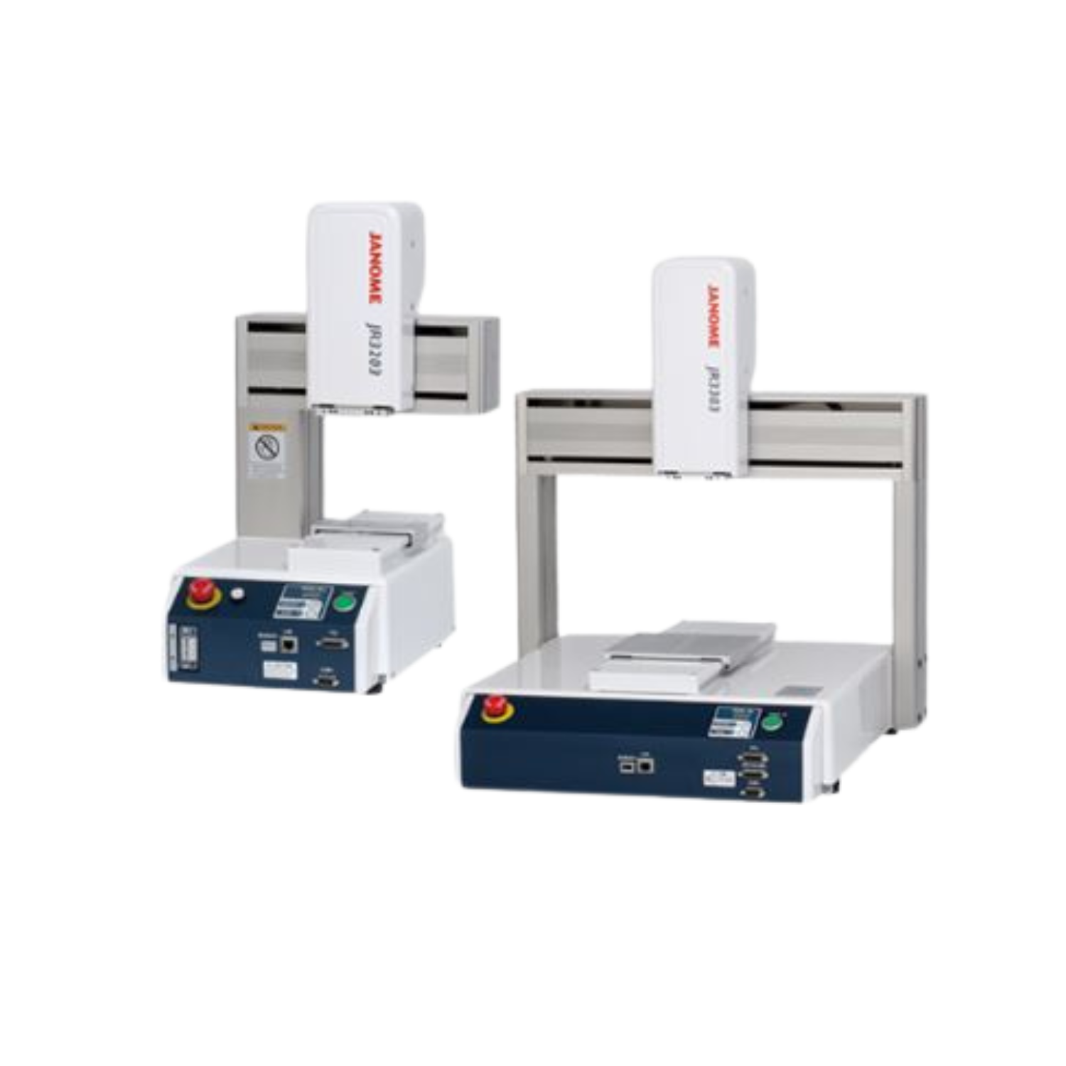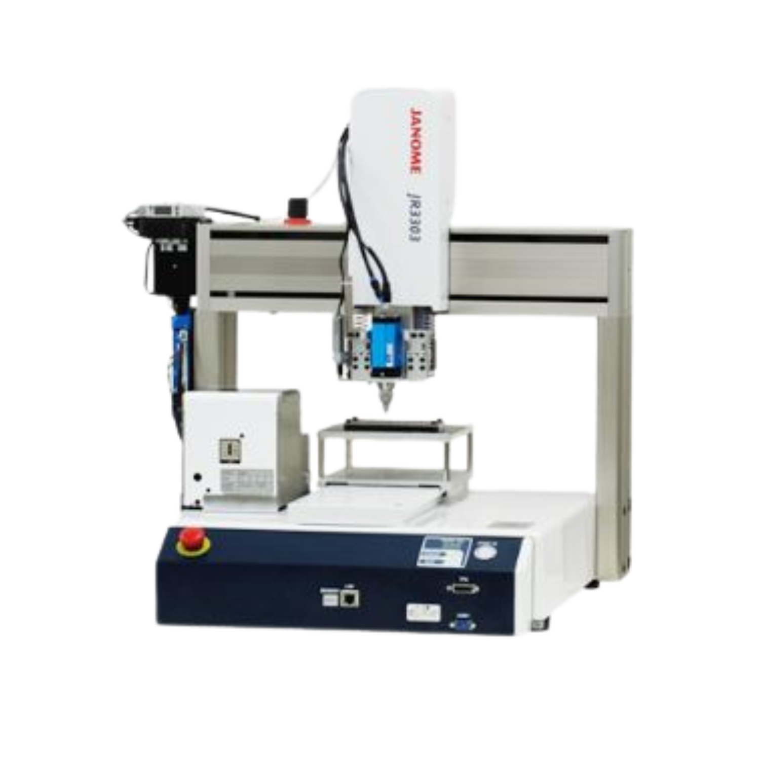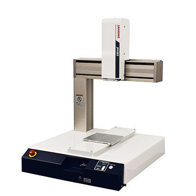
Desktop Robot JR4000 Series (Models: JR4203, JR4204, JR4303, JR4304, JR4403, JR4404, JR4503, JR4504 JR4603, JR4604)

Product Code : DE2331
Brand: JANOME
Availability: Đặt trước
Contact

Features

Increased Maximum Speed & Acceleration

Attained maximum speed of 1000mm/sec and maximum acceleration of 3400mm/sec2 with the JR43000 and larger models.
Industry-leading speed shortens cycle time.

Increased Maximum Speed & Acceleration

Device Attachment Grooves

The top and rear of the Y Axis arm feature grooves for attaching external devices.
Easily consolidate wiring when attaching external tools, etc.

Device Attachment Grooves

Selectable Safety Circuit (optional)

In addition to the conventional Safety Category 1, Performance Level PL=c circuit, it is possible to select the option of constructing an external Safety Category 3, Performance Level PL=d safety circuit (with a motor power supply turn OFF) for dangerous jobs and/or facilities.

Selectable Safety Circuit (optional)

Optional auxiliary axes function for control of up to 4 axes + 2 external motors

Connect up to 2 "pulse string input type" devices, such as stepping motors or servomotors.
2 control modes and an encoder input function for compatibility with a variety of applications.

①Point Mode The auxiliary axes move in tandem with the robot's X, Y, Z and R Axes.
Example: a 4 Axes dispensing robot expands to 6 axes.
2 axes are added to change both the syringe angle and the workpiece angle to set the angles for dispensing on the outer edge surface of a hole cut into a tubular workpiece.
② Independent Mode The auxiliary axes move independent of the robot's X, Y, Z and R Axes.
Example: Have the robot do a job while running a conveyor.
The auxiliary axis (or axes) operate independent of the point coordinates and movements, allowing the robot to execute jobs such as dispensing or screw tightening while the conveyor runs.
③ Encoder Input Acquire external encoder values and monitor the rotation amount; also control sensors.

Camera System

With an optional AS200 position adjustment camera, make position corrections for displaced workpieces for accurate jobs.
No need for specialized camera software; both the robot and the camera are settable with our original "JR C-Points III" software.

Auto Calibration
Auto Calibration                                       Camera Position Adjustment
                       Auto Calibration                                                                                  Camera Position Adjustment
 

Expanded Fieldbus Compatibility

In addition to the signal control and point job-based data exchange functions from our previous model, we added a "Fieldbus Register Output Function" to the JR4000 for constant output of specified types of data, which allows the user to consistently acquire necessary data from a PLC with making complicated settings.

Expanded Point Jobs & Customization Functions

Freely program the robot with point jobs, even with jobs for which there are no preset point types.
Compared with our previous model, the JR4000 offers more usable commands and built-in variables and expanded function customization capabilities.


*Other features such as user-friendly teaching, needle adjuster functions, etc., are carried over from the JR3000 Series.

PC Software "JR C-Points Ⅲ" (optional)

Janome's original PC software "JR C-Points III" is a comprehensive interactive program input system allowing users to create, edit and save teaching data and customizing data all on their PC.
Show movement point coordinates graphically to instinctively grasp program content, as well as convert coordinates from CAD data. Setting parameters are also shown in the convenient tree view for confirmation and editing.
Convert "JR C-Points II" teaching data into "JR C-Points III" data for use with the JR4000.

① Ribbon Control
Click each category tab and the function buttons and setting items for that tab appear.

② Graphic Editing View
Teach visually with the 3D view in the 3D display graphic editing area.

③ Point Data Editing View
Directly edit the selected point data elements, including the point type, coordinate positions, point job, etc.

④ JOG View
Connect to the JR4000 Robot and make JOG movements directly from a PC.

PC Software JR C-Points Ⅲ (optional)

Greatly Enhanced Point Graphic Functions

3DCAD Upload Capability

Referring to uploaded 3DCAD data, automatically generate teaching points, and greatly reduce your teaching burden.
A new point type, "Spline Curve Drive" is built into the system program, making it possible to handle even workpieces with difficult shapes.

3DCAD Upload Capability
Easily Adjust Registered Point Coordinates

Easily offset, enlarge or reduce the coordinate image on the graphic display.
Adjust the coordinates to match the actual robot for easy operation.

Easily Adjust Registered Point Coordinates

Quick Guide

Select a menu item or function and the "Quick Guide" shows an explanation of that selection on the PC software display. There is no need to take out the operation manual just to confirm the content of a given function.

Quick Guide

Tablet PC Compatibility

Change user interfaces between a standard PC and a tablet PC.
Operate the robot comfortably even in different environments.

Tablet PC Compatibility

*For safety, use a Safety Commander© when using a tablet PC.
*Safety Commander© is a trademark and/or registered trademark of IDEC CORPORATION.

Coordinate Conversion Function for Workpiece Variation Adjustment

Converts the job coordinates to match the coordinates for each individual workpiece written to the software to compensate for individual variations when doing the same job on multiple workpieces. Horizontal deployment is more efficient as the additional effort for making fine adjustments is eliminated.

Operation Lock Function

Set a password from a Windows account with administrator rights, and lock the data so it cannot be saved or overwritten from other accounts.

Software Applications

Dedicated software for screw tightening and dispensing jobs.

Screw Tightening Specifications

Creating screw tightening job programs is easy: just set the job positions for screw tightening parameters such as screw pitch, length, and the driver rpm.

Screw Tightening Specifications

  • Not just full screw tightening, but teaching screw loosening and partial (loose) screw tightening is also easy.
    (Loosening operations need to coordination from the screwdriver side.)
  • Screw Tightening Error Detection Function
    Specialized screw tightening software features helpful functions including "Screw Stop Detection", "Screw Float Detection" as well as a function to stop the robot when the screw feeder is empty.

Application Example

Application Example

Robot with screwdriver and screw feeder attached.


Dispensing Specifications

Creating dispensing programs is easy: just set the job positions for dispensing parameters such as point dispensing or line dispensing.

Dispensing Specifications

  • Fill-in Dispensing Function
    Convenient fill-in dispensing functions which allow you to dispense like drawing a picture using only 2 points for a rectangle and 3 points for a circle.
  • Purging Function
    Have the robot purge on a repeating cycle when holding at the work home position. Also, purge the dispensing liquid whenever you want using the optional "Purge Switch".
  • Fragmented Dispensing Prevention Function
    Set a waiting time to prevent fragmented dispensing at the beginning and spraying at the end of dispensing runs.

Application Example

Robot with dispensing unit attached


How to Read the Model Code

                                 Example                                                    Example
(1)
Device Type
(2)
X-Y Axes
Stroke(mm)
(3)
Number of Axes
(4)
Encoder*1
(5)
Operation Panel Specifications
(6)
Power Supply Specifications
(7)
CE Declaration
JR4000 Series 20:200×200
30:300×320
40:400×400
50:510×510
60:510×620
3:
3 Axes
4:
4 Axes
E:Encoder Included
N:Without Encoder
A:Installed Switch Spec
B:Switchbox Spec
C:Custom Switch Spec
0:100-120/200-240V 50/60Hz (No outlet)
1:100-120V 50/60Hz (100V outlet)*2
2:200-240V 50/60Hz (200V outlet)*2
A:Not Declared
(for sale in Japan only)
B:Declared
(Power Supply
Specifications:0 only)
  • *1 Motor Synchronization Error Detection Function
  • *2 The JR4200 CE Declared, with I/O-S2 added type has no outlet.


Product Lineup

Model JR4203 JR4204 JR4303 JR4304 JR4403 JR4404 JR4503 JR4504 JR4603 JR4604
X-Y Axes Stroke(mm) 200×200 300×320 400×400 510×510 510×620
Number of Axes 3 4 3 4 3 4 3 4 3 4
Encoder E:Encoder Included / N:Without Encoder
Operation Panel Specifications ※This example is for the JR4200 Series.
      
A: Installed Switch Spec  B: Switchbox Spec  C: Custom Switch Spec
Power Supply Specifications 0: 100-120/200-240V 50/60Hz (No outlet)
1: 100-120V 50/60Hz (100V outlet)*1
2: 200-240V 50/60Hz (200V outlet)*1
Optional Specifications Field Network
(CC-Link, EtherNet/IP, PROFINET)
○ ○ ○ ○ ○ ○ ○ ○ ○ ○
I/O-SYS Add-on
(16 inputs / 16 outputs)
○ ○ ○ ○ ○ ○ ○ ○ ○ ○
I/O-1 Add-on
(16 inputs / 14 outputs)
○ ○ ○ ○ ○ ○ ○ ○ ○ ○
I/O-MT Add-on
(for controls
auxiliary axes)
○ ○ ○ ○ ○ ○ ○ ○ ○ ○
ENC-IN Add-on *2
(for external
encoder value input)
○ ○ ○ ○ ○ ○ ○ ○ ○ ○
I/O-S *3
(for interlock
device connection)
○ ○ ○ ○ ○ ○ ○ ○ ○ ○
I/O-S2 *3
(for interlock
device connection)
- - ○ ○ ○ ○ ○ ○ ○ ○
Rear Side LAN Port ○ ○ ○ ○ ○ ○ ○ ○ ○ ○
Double Sided - - Standard Standard ○ ○ - - - -
Elevated Column
(Open Height Variation)
○ ○ ○ ○ ○ ○ ○ ○ ○ ○
Optional Switch*4 ○ ○ ○ ○ ○ ○ ○ ○ ○ ○
Added built-in
I/O power supply
(DC24V rated 2.1A)
○ ○ ○ ○ ○ ○ ○ ○ ○ ○
COM1・2・3*2 Add-on
(for external devices)
○ ○ ○ ○ ○ ○ ○ ○ ○ ○
Ejector (air suction
for screw tightening)
○ ○ ○ ○ ○ ○ ○ ○ ○ ○
  • *1 The JR4200 CE Declared, with I/O-S2 added type has no outlet.
  • *2 Either only the ENC-IN connector or only the COM3 connector is available, but not both.
  • *3 Either only I/O-S or only I/O-S2 is available, but not both.
  • *4 With the Type B and Type C Operation Panels, the Optional Switch is added to the Switchbox.


Main Specifications

3 Axes

  JR4203 JR4303 JR4403 JR4503 JR4603
Operating Range X・Y Axes 200×200mm 300×320mm 400×400mm 510×510mm 510×620mm
Z Axes 50mm 100mm 150mm
Maximum Portable
Load
Workpiece 7kg 15kg
Tool 3.5kg 7kg
Maximum Speed
*1
<PTP Movement>
( )=setting range
X・Y Axes 700mm/s
(7~700)
1000mm/s
(10~1000)
Z Axes 250mm/s
(2.5~250)
400mm/s
(4~400)
Maximum Speed
*1
<CP Movement>
=setting range
X・Y・Z
Combined
Speed
600mm/s
(0.1~600)
850mm/s
(0.1~850)
Repeatability *2 X Axes ±0.006mm ±0.007mm ±0.008mm ±0.008mm
Y Axes ±0.01mm
Z Axes ±0.008mm
External Dimensions*3
( )=Double Column Type
W×D×H
*excluding protrusions
323×389×554mm 560×535×659mm 584×630×807mm
(615×631×807)
678×730×807mm 790×730×807mm
Main Unit Weight*3
( )=Double Column Type
20kg 36kg 42kg
(45)
45kg 46kg

4 Axes

  JR4204 JR4304 JR4404 JR4504 JR4604
Operating Range X・Y Axes 200×200mm 300×320mm 400×400mm 510×510mm 510×620mm
Z Axes 50mm 100mm 150mm
R Axes ±360°
Maximum Portable Load Workpiece 7kg 15kg
Tool 3.5kg 7kg
Maximum Speed*1
<PTP Movement>
( )=setting range
X・Y Axes 700mm/s
(7~700)
1000mm/s
(10~1000)
Z Axes 250mm/s
(2.5~250)
400mm/s
(4~400)
R Axes 600°/s
(6~600)
900°/s
(9~900)
Maximum Speed*1
<CP Movement>
( )=setting range
X・Y・Z
Combined
Speed
600mm/s
(0.1~600)
850mm/s
(0.1~850)
Acceptable Moment of Inertia 65kg・cm² 90kg・cm²
Repeatability *2 X Axes ±0.006mm ±0.007mm ±0.008mm
Y Axes ±0.01mm
Z Axes ±0.01mm
R Axes ±0.008°
External Dimensions*3
( )=Double Column Type
W×D×H
*excluding protrusions
323×389×676mm 560×535×844mm 584×630×894mm
(615×630×894)
678×730×894mm 790×730×894mm
Main Unit Weight*3
( )=Double Column Type
22kg 39kg 46kg
(49)
49kg 50kg
  • *1 Maximum speed can vary depending upon conditions. The robot cannot reach maximum speed when bearing the maximum portable load.
  • *2 Position repeatability is not a guarantee of absolute precision.
  • *3 With optional specifications, the external dimensions and the robot's mass may change. Please contact us. for details.

Common Specifications

Drive Method 5 phase pulse motor drive (encoder added as an option)
Control Method TP (Point to Point) control, CP (Continuous Path) control
Interpolation 3-dimensional linear, 3-dimensional arc interpolation and spline curve interpolation
Teaching System Remote teaching (JOG) / Manual Data Input (MDI)
Teaching Method ・Direct teaching using the optional teaching pendant
・Off-line teaching with "JR C-Points Ⅲ" software from a PC. Compatible with CAD graphics(DXF, STEP, IGES, DWG, JPEG).
Screen Display Languages Japanese・English・French・Spanish・Italian・German・Korean・Simplified Chinese・Traditional Chinese・Czech・Vietnamese
Program Capacity 999 programs
Data Capacity Up to 32,000 Points*4
Simple PLC Function Up to 100 programs, with up to 1,000 steps/program
External Input/Output I/O-SYS*5
(optional)
16 inputs, 16 Outputs
I/O-1*5
(optional)
16 inputs, 14 Outputs (including 2 relay outputs)
I/O-S*6
(optional)
Interlock connector for an area sensor,etc. ①I/O-S1: Standard Safety Circuit ②I/O-S2: Redundant Safety Circuit
I/O-MT
(optional)
For auxiliary axes (pulse string input type*7)control;
control up to 2 axes
Field Network
(optional)
CC-Link, EtherNet/IP, PROFINET
COM1(optional) RS-232C for external device control, COM commands
COM2、COM3*8
(optional)
RS-232C for external device control
LAN*9 Ethernet connector for PC
・Robot control via control commands
・Connection to (optional) PC software "JR C-Points Ⅲ"
 (Send and receive teaching and customizing data, upgrade system software)
 (Optional: rear side port installation)
ENC-IN*8
(optional)
For external encoder value input
TPU Dedicated teaching pendant connector (optional)
SWITCHBOX*10 Dedicated switchbox connector
I/O Built-in Power Supply(optional) 24V Rated 2.1A
Power Source AC100-120V/200-240V (Single Phase) 50/60Hz
Power Consumption 200W
Operating Enviroment Temperature 0~40°C
Relative Humidity 20~90% (Without condensation)

Reference Diagram *JR4200 Series (Operation Panel Specification A Standard Type)

  • *4 Point data memory capacity reduces as additional function data, point job data and sequencer data increase due to the shared storage area.
  • *5 There are 2 I/O polarity types available: PNP and NPN.
  • *6 I/O-S2 is not available with 200mm stroke models.
  • *7 Please prepare a control power supply, pulse motor and motor driver at your side.
  • *8 It is possible to add only COM3 or ENC-IN, but not both.
  • *9 The Ethernet connection is 10BASE/100BASE-T.
  • *10 The Operation Panel is Type B only.
  • Optional specifications are available only when placing your order; no post-order modifications.
  • CE declared models are also available.
  • Specifications may change without prior notice to improve product quality.

Standard Accessories

  • Common: Power Cable

Optional Attachments

  •  Common:
    ・PC Software "JR C-PointsⅢ" (Windows®10 64bit, Windows®11 compatible) Switch among Japanese and English.
    ・I/O-SYS Connector
    ・I/O-SYS Cable (2m/3m/5m)
    ・I/O-SYS Terminal Block (0.5m/2m)
    ・I/O-1 Connector
    ・I/O-1 Cable (2m/3m/5m)
    ・I/O-1 Terminal Block(0.5m/2m)
    ・I/O-MT Connector
    ・I/O-MT Cable (0.5m/1m/3m/5m/10m)
    ・ENC-IN Connector
    ・AS200 Position Adjustment Camera
    ・Needle Adjuster
    ・Cable Carrier (Standard Models and Dispensing Models only)
    ・Teaching Pendant (2m/3m/5m)
    - Standard type
    - With Emergency Stop Switch
    - With Enable Switch
    - With Mode Changing Switch
    - With Emergency Stop Switch + Enable Switch
    - With Emergency Stop Switch + Mode Changing Switch
    - With Enable Switch + Mode Changing Switch
    - With Emergency Stop Switch + Enable Switch + Mode Changing Switch
  • Operation Panel Specification B Type:
    ・Switchbox(2m/3m/5m)
    - Standard type
    - With Mode Changing Switch
    - With Optional Switch
    - With Mode Changing Switch + Optional Switch

Reviews Desktop Robot JR4000 Series (Models: JR4203, JR4204, JR4303, JR4304, JR4403, JR4404, JR4503, JR4504 JR4603, JR4604)

0/5 (0 Reviews )
5
0%
4
0%
3
0%
2
0%
1
0%

Bạn chưa đánh giá sao cho sản phẩm này

Đánh giá ngay

Đánh giá của bạn về sản phẩm:


Very bad


Bad


Normal


Good


Very good